| Issue |
Manufacturing Rev.
Volume 12, 2025
|
|
|---|---|---|
| Article Number | 23 | |
| Number of page(s) | 12 | |
| DOI | https://doi.org/10.1051/mfreview/2025018 | |
| Published online | 14 October 2025 | |
Original Article
Effect of fluid pressure on the thickness distribution of single-layer and double-layer cups
Hanoi University of Science and Technology, Hanoi, Vietnam
* e-mail: This email address is being protected from spambots. You need JavaScript enabled to view it.
Received:
29
March
2025
Accepted:
6
September
2025
Abstract
In recent years, sheet hydrostatic forming technology has been widely applied to the production of thin-shell components due to its advantages and suitability. The blank is shaped to match the contour of the die under the influence of high-pressure fluid. Therefore, understanding the deformation of the blank under this fluid pressure is essential. While numerous studies have focused on single-layer material blanks, further research is needed on multilayer material blanks. This study examines the behaviors of single-layer and double-layer materials during the hydrostatic forming process. The results reveal differences in the forming process for cylindrical products made from single- and double-layer materials. Graphs illustrating the influence of various process parameters on product quality and the contribution of each material layer in double-layer materials are also presented. The study explores the impact of fluid pressure on sheet thinning and methods to enhance the forming ability through simulations and experiments. The simulation results show a reasonable agreement with experimental observations. These findings facilitate the assessment and prediction of forming outcomes, providing a foundation for future research.
Key words: Sheet hydroforming / hydrostatic forming / single-layer / double-layer / metal forming
© M.-Q. Nguyen et al., Published by EDP Sciences 2025
 This is an Open Access article distributed under the terms of the Creative Commons Attribution License (https://creativecommons.org/licenses/by/4.0), which permits unrestricted use, distribution, and reproduction in any medium, provided the original work is properly cited.
1 Introduction
Multilayered sheets consist of several layers with different properties. By combining various materials, multilayer sheets can offer advantageous characteristics such as high thermal conductivity, damage resistance, excellent bending stiffness, and superior surface quality [1–8]. Integrating different layers has also shown potential for enhancing the mechanical properties of multilayer materials [9–12]. One notable advantage of two-layer sheet metals is the ability to simultaneously form materials with different plasticity. Higher-plasticity material is used to control the deformation process of the lower-plasticity material. Consequently, the forming ability of low-plasticity materials was effectively enhanced [13]. Multilayer materials also significantly improve anti-fatigue performance by limiting crack propagation between layers. Due to these advantages, multilayer sheets are used in various industries, including aerospace, automotive, electronics, and maritime, offering innovative features compared to conventional metallic sheets [14–17]. Sakaki et al. conducted the first studies on analytical models of bimetallic sheets [18]. Based on Hills' theory, they presented a continuum mechanics model to investigate the plastic deformation of clad sheets.
In recent years, many investigations have focused on the forming processes of double-layer sheets using traditional methods such as deep drawing and bending. In 1996, Kurimoto and Mori [19] studied the formability of cladding sheets through press-forming tests. They found that the higher-strength component had a more significant impact on the drawing ratio in the deep-drawing process of bimetallic sheets. Furthermore, they observed that the forming ability for stretching and deep drawing improved when the aluminum layer was positioned on the outer side of the cup. Taheri and Manesh [20] investigated the cold rolling of tri-layer strips.
In studies involving rolling sandwich strips, aluminum, mild steel, and copper were used as layers. Lang et al. [21] also investigated multi-sheet hydroforming, employing a thin middle layer. They examined the impact of various parameters on the forming process and explored methods to enhance sheet formability through experimentation and simulation. Pazand et al. [22] evaluated the formability of three-layer metallic sheets with different layer arrangements, both experimentally and numerically. They found that the forming limit diagrams (FLDs) of the three-layer sheets were significantly affected by the arrangement of the layers relative to the punch. Notably, the mechanical properties of the inner layer, especially its strength, had a substantial influence on the formability of the three-layer sheets. Liu et al. [23] Researched hydroforming for the production of double-layer sheets. By comparing parts formed using hydroforming with single-layer and double-layer sheets, they found that the presence of an upper sheet improved overall plastic strain uniformity, enhanced wall thickness consistency, and reduced maximum thinning rates.
In conventional forming processes, eliminating defects, such as wrinkling and fractures in the noncontact areas of parts is challenging. Heat treatment, ironing, and multistep forming are often required to resolve these issues, making the processes complex and time-consuming [24]. In contrast, hydrostatic forming technology can effectively reduce defects in the non-contact areas of parts by providing uniform pressure loading, which is beneficial for multilayer sheet forming and ensures that the layers maintain tight contact with each other. For this reason, hydrostatic forming technology was chosen for the simultaneous forming of double-layer sheet metals with different. However, it is essential to investigate the deformation of the layers under high-pressure fluid. This study evaluated the forming behavior of a double-layer sheet in terms of thickness distribution during both the free bulging and finishing stages. Additionally, the influence of hydraulic pressure on the target layer was analyzed. An equation was established to describe the relationship between fluid-forming pressure and maximum thinning. The finite element method was employed for numerical simulation, and experimental studies were conducted to verify the findings. This research aims to enhance the understanding of the forming behavior of double-layer sheet and pave the way for further studies on this specialized material.
While many studies have focused on bonded double-layer sheets, the forming behavior of unbonded sheets − where layers interact via friction − has received little attention. This study addresses that gap by investigating the deformation behavior of unbonded double-layer sheets under hydrostatic forming, which is crucial for applications where bonding is not applied.
2 Material and methods
2.1 Objectives
The primary objective of this study was to investigate the forming behavior of double-layer materials in the production of a cylindrical cup using hydrostatic technology, focusing on the effects of key parameters on the thinning distribution of the final product. Additionally, material with superior mechanical properties was used as the outer layer to enhance the formability of the inner, less ductile material.
The two materials used were low-carbon steel DC04 and copper (Cu). Due to copper's lower deformation capability compared to DC04 steel, DC04 was employed as the outer layer to improve the formability of copper, which served as the target layer.
The critical parameters investigated were the forming fluid pressure (P) and the arrangement of the layers. The impact of layer arrangement refers to how the positioning of the individual layers in double-layer materials can influence their performance. In this study, the inner layer was in direct contact with the fluid, while the outer layer contacted the die cavity. The roles of the two layers were alternated to determine the optimal configuration. Two cases were considered: Cu/DC04 (with DC04 as the outer layer) and DC04/Cu (with Cu as the outer layer).
The relationship between forming fluid pressure and the maximum thinning of the target layer was also established. The study specifically assessed the thickness distribution of the final product. Numerical simulations, verified through experimental methods, were conducted to achieve the objectives outlined above. The experimental results provided a basis for evaluating the simulated outcomes of the hydrostatic forming process used to produce cylindrical cups from double-layer material blanks.
2.2 Double-layer sheet principal analysis
Figure 1 illustrates the hydrostatic forming principle for double-layer sheets. The formability of the plate can be intentionally enhanced by using an outer layer with superior mechanical properties. Simultaneously, the forming limit can be improved through beneficial interfacial friction between the two layers and appropriate drawing parameters. Due to the different spring back behaviors of the layers after forming, they naturally separate, producing the desired part.
In the hydrostatic formation of a double-layer sheet, the mechanical properties of the outer sheet must meet the following requirements:
The yield strength of the outer sheet should exceed that of the target sheet. The outer sheet undergoes plastic deformation because the target sheet yields earlier in the forming process.
The tensile strength of the outer sheet should be higher than that of the target sheet. When excessive hydraulic pressure is applied, the outer layer should have a lower tendency to fracture than the target sheet, preventing poor forming quality in the target layer due to fractures in the outer sheet.
The elastic modulus of each layer should differ significantly. This allows the layers to separate after forming, as the differing spring back values help achieve the target part.
Therefore, low-carbon steel DC04 and copper were chosen as the sheet materials. The mechanical properties of the outer and target sheets that met the selection criteria were compared.
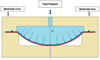 |
Fig. 1 Schematic of double-layer sheet in hydrostatic forming. |
2.3 Material
This investigation focuses on copper (Cu) and low-carbon steel DC04. The constitutive model used for both materials assumes that elastic behavior is isotropic and follows the generalized Hooke's law, and the plastic behavior is characterized by the von Mises yield criterion with isotropic hardening, along with the associated flow rule. Swift's law is employed to describe the isotropic hardening behavior of these metallic materials.
 (1)
(1)
In this model as shown in equation (1), Y represents the yield stress and its evolution with equivalent plastic strain, K, ε, ε0, and n are material parameters; Y= K(ε + ε0)n is the initial yield stress. Tensile specimens were used to construct constitutive models for DC04 and Cu. The specimens, prepared through wire cutting, are shown on Figure 2. Table 1 provides the parameters for the Swift's law and the elastic properties according to Hooke's law (Young's modulus, E, and Poisson's ratio, v) for the two materials.
Figure 3 shows the differences in hardening behavior between steel DC04 and copper Cu, allowing for a detailed investigation of their effects on the material mechanical properties.
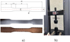 |
Fig. 2 The uniaxial tensile test: (a) Tensile specimens, (b) MTS testing machine. |
Material properties and parameters.
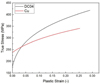 |
Fig. 3 Stress-plastic strain curves. |
3 Results
3.1 Numerical simulation scheme design
3.1.1 Numerical condition
The study focuses on a cylindrical cup, with dimensions shown in Figure 4 and listed in Table 2. This type of product is commonly used in metal-forming research.
The finite element method was utilized to analyze and verify the forming ability of double-layer sheets during hydrostatic forming. The cup-forming simulation was performed using ABAQUS/CAE software. For the hydrostatic process, the large-deformation behavior of the double-layer sheet was modeled with ABAQUS/Explicit, and only one-quarter of the test geometry was simulated due to material and geometric symmetries. In the numerical model, isotropic plastic behavior was assumed for the sheet materials and its influence on the forming results is considered in the discussion comparing the experimental and simulation outcomes.
Material properties were determined from tensile tests. The blank was meshed with quadrilateral shell elements, while the die and holder plates were treated as discrete rigid bodies. In the finite element model, the approximate global element size was set to 1.0 mm in ABAQUS, based on a mesh sensitivity study to ensure result convergence and computational efficiency. The Ductile Damage Criterion available in ABAQUS/Explicit was employed to simulate and predict fracture initiation. The blank holder's movement was restricted to the vertical direction, allowing for changes in blank thickness during forming. Additionally, to replicate the hydraulic pressure during SHF simulation accurately, the idea of applying a thin film was applied as shown in Figure 5a. In FE model, a thin shell element (0.01 mm thickness) with smaller Young's module was set above the inner layer. The friction coefficient for the contact between inner layer and thin film was fixed at zero. The contact behavior of the inner layer-virtual film enables the hydraulic loading to be translated from the film to the inner layer realistically. On the formed parts, the node path from the center point to the edge node was selected along the radius direction, as shown in Figure 6. The coordinates of each element node are used to represent the contour shape of the parts.
 |
Fig. 4 The specific part size. |
Geometrical conditions.
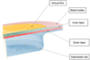 |
Fig. 5 The finite element model of double-layer sheet in hydrostatic forming. |
 |
Fig. 6 Path of nodes. |
3.1.2 The impact of layer arrangement
To investigate the effect of layer arrangement, two configurations were analyzed: Cu/DC04 (DC04 as the outer layer) and DC04/Cu (Cu as the outer layer). In the simulation, the coefficient of friction between the workpiece and the forming die was set to 0.1, assuming lubricated with a polymer layer [25].
The simulation results indicated that the maximum critical pressures were Pmax = 48 MPa for the Cu/DC04 arrangement and Pmax = 42 MPa for the DC04/Cu arrangement. When the maximum critical pressure was exceeded, tearing tended to occur first at the bottom radius of the Cu layer in both cases, as shown in Figures 7b and 8b. According to the Abaqus simulation results, STH represents sheet thickness (in Millimeters, mm), and S denotes stress (in Megapascals, MPa). These results suggest that the maximum critical pressure in the Cu/DC04 configuration was higher than in the DC04/Cu configuration. Understanding the stress state in low-carbon steel helps explain the differences in forming capability. In the outer layer, both biaxial and bending tensions are present near the bottom radius, where cracks form, while bending compression helps alleviate tension in the inner layer [19]. Figures 7a and 8a show the simulation results for the product at 42 MPa and 48 MPa, respectively.
In the DC04/Cu configuration, the maximum critical pressure was Pmax = 42 MPa. To compare the thickness distribution between the two configurations, simulations at a pressure of 42 MPa were performed for both the DC04/Cu and Cu/DC04 conditions. Figure 9 presents the thickness distribution along the path of the target Cu layer in both cases at P = 42 MPa. The results indicate that, at the bottom radius, the target Cu layer in the DC04/Cu arrangement (with Cu as the outer layer) experienced significantly greater thinning. This extensive thinning could lead to the rapid failure of the blanks. In contrast, when Cu was the inner layer (Cu/DC04), the thickness reduction in the Cu layer was less pronounced, resulting in improved formability due to the presence of the outer DC04 layer.
 |
Fig. 7 Cu layer in DC04/Cu case (a) 42 MPa (b) Exceeding 42 MPa. |
 |
Fig. 8 Cu layer in Cu/DC04 case (a) 48 MPa (b) Exceeding 48 MPa. |
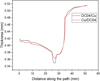 |
Fig. 9 Wall thickness distribution of target Cu sheet at 42 MPa. |
3.1.3 Analysis of single-sheet and double-layer sheet hydrostatic forming
Simulations were conducted to analyze the forming process for both single-layer and double-layer Cu/DC04 sheets, using Cu with a thickness of 0.5 mm. The thickness distribution was compared.
Hydrostatic forming of a cylindrical cup involves two distinct stages: the free-bulging stage and the finishing stage. Figures 10 and 11 show the thickness distribution of the Cu layer during these stages for both single-layer and double-layer sheet hydrostatic forming. Figures 10a,10b illustrates the free-bulging stage, while Figures 11a,11b depicts the finishing stage, focusing on the deformation at the bottom radius.
During the free-bulging stage, with the same final product shape, the dome height − denoted as Up − was identical in both cases, with a value of 15.13 mm, the thinnest point of the Cu sheet in the single-layer configuration was 0.414 mm, with a maximum thinning rate of 17.2%. In the double-layer configuration, the thinnest point was 0.44 mm, and the maximum thinning rate was 12%. Maximum thinning rate refers to the highest percentage reduction in sheet thickness during deformation, compared to its original thickness.
During the finishing stage, it can be observed that at the same final product shape, with a bottom radius of 23.18 mm, the single-layer Cu sheet experienced significantly greater thinning compared to the Cu layer in the double-layer sheet. The minimum thickness of the single Cu sheet was 0.37 mm, corresponding to a maximum thinning rate of 26%.
A comparison of the wall thicknesses in Figure 12a shows that in the double-layer hydrostatic forming process, the outer sheet (DC04) significantly influences the thinning distribution of the target Cu layer, even though the maximum thinning point in both cases remains at the dome's peak. For the same product shape, the single-layer Cu sheet exhibited more substantial thinning than the double-layer configuration at the surveyed positions as shown in Figure 12b. The presence of the outer layer has a positive effect, enhancing the formability of the weaker inner layer. This characteristic can be further utilized to improve the deformability of even thinner inner layers.
 |
Fig. 10 Wall thickness distribution of Cu layer in the free bulging stage (a) single-layer (b) double −layer. |
 |
Fig. 11 Wall thickness distribution of Cu layer in the finishing stage: (a) single-layer and (b) double −layer. |
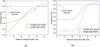 |
Fig. 12 The formed copper Cu thickness comparison (a) Free bulging stage (b) Finishing stage. |
3.1.4 Influence of hydraulic pressure on the target layer
For the simulation, the target layer is Copper DC04 as mentioned above and the outer sheet DC04, with a thickness of 0.5 mm, was selected. The entire forming process was divided into a 5-second time step, with 0÷4.8 seconds representing the drawing phase and 4.8÷5 seconds corresponding to the pressure maintenance phase. The fluid pressure was simulated in ABAQUS by gradually increasing the pressure from 0 to 50 MPa.
The contour shapes of the parts were represented by the coordinates of each element node. Figure 13 displays a comparison of contour shapes under different hydraulic pressures, clearly showing that the fitness of the parts improves as the hydraulic pressure increases.
As hydraulic pressure increases, the location of the thinnest section of the product shifts during each stage, including the free-bulging and cup bottom forming stages, as depicted in Figure 14.
At a low pressure of 8 MPa (Fig. 15a), the deformation of the Cu layer takes on a dome shape during the free bulging stage, with the most significant deformation occurring at the peak of the dome. As the pressure increases to 10 MPa and beyond (Figs. 15b,15c,15d), and the material layers meet the bottom part of the cylindrical cup, the most substantial thinning occurs at the bottom radius. This region is prone to cracking and represents a critical risk area during the finishing stage of the cylindrical cup formation.
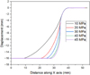 |
Fig. 13 The target part Cu contour under different hydraulic pressures. |
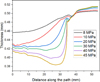 |
Fig. 14 The target Cu sheet thickness distribution under different hydraulic pressures. |
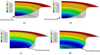 |
Fig. 15 Wall thickness distribution (a) 8 MPa (b) 10 MPa (c) 30 MPa (b) 40 MPa. |
3.1.5 Fluid forming pressure − Maximum thinning equation
This section discusses the influence of fluid forming pressure (P) on the maximum thinning (y) of the target Cu sheet in the Cu/DC04 configuration across two stages—free bulging and finishing. The term “maximum thinning” refers to the minimum wall thickness observed in the formed part, representing the thinnest position of the product after forming. The relationship between these variables was formulated as an equation. As noted earlier, during the free bulging stage, the maximum thinning occurs at the dome's peak, while in the finishing stage, it typically appears at the bottom of the rounded radius. The simulation parameters used were a blank holder force Q of 30 kN and a friction coefficient between the layers of 0.15. In this study, equation (2) was empirically developed by fitting experimental data using Origin software to describe the relationship between hydroforming pressure (P, in MPa) and the maximum thinning (y, in mm). In this model, y0 (mm) represents the initial sheet thickness at zero pressure, A is the exponential decay amplitude indicating the initial difference from y0 and t is the decay rate parameter that characterizes the sensitivity of thinning to pressure changes.
 (2)
(2)
This equation serves as not only a computational tool but also an objective approach for describing and predicting material-forming phenomena. To assess the accuracy of the model, the R2 coefficient was used to measure the degree of fit between the equation and the simulation data. The R2 coefficient is a crucial indicator for quantifying a model's ability to explain the variability in empirical data. An R2 value very close to 1 signifies that the model can explain a substantial portion of the data variation.
During the free bulging stage, using Origin software, the coefficients of equation (2) were determined with R2 = 1, therefore equation (2) is rewritten as equation (3).
 (3)
(3)
The results demonstrate a high R2 value, R2 = 1, indicating a strong alignment between equation (3) and the simulation data.
During the finishing stage, the coefficients of equation (2) are determined with the R2 = 0.99, therefore equation (2) is rewritten as equation (4).
 (4)
(4)
Figures 16 and 17 illustrate the relationship between the forming fluid pressure (P) and the maximum thinning (y) of the target sheet (Cu layer) during the free bulging and finishing stages, respectively. The close overlap of the two curves confirms a strong consistency between the simulation results and the predictions made by the equations. This alignment supports the validity of the mathematical model in accurately capturing the behavior of the system.
With the equation coefficients provided in Table 3, these formulations help predict the maximum thinning during the forming stages. The equation not only describes a governing principle of the forming process but also serves as a practical computational tool for forecasting outcomes under different conditions. This is especially beneficial for optimizing manufacturing processes, anticipating variations in product quality, and making necessary adjustments to achieve desired results.
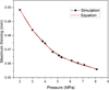 |
Fig. 16 Pressure-maximum thinning in bulging stage of Cu layer. |
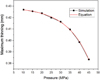 |
Fig. 17 Pressure-maximum thinning in finishing stage of Cu layer. |
The coefficients of the Pressure-maximum thinning equation.
3.2 Experimental study on double-layer sheet hydrostatic forming
3.2.1 Experimental scheme design
To validate the analytical results, a comparison was made between the simulation and experimental findings, focusing on the product thickness at specific measurement points (Fig. 18).
Figure 18 illustrates the components of the hydrostatic die used in experiments. A 125-ton hydraulic press was used in this study, capable of generating up to 1,225 kN of compressive force. Before starting the experiment, the target sheet was a copper Cu blank and the outer layer was a low-carbon steel DC04 blank, each blank has a diameter of 110 mm with 0.5 mm thickness. The initial processing parameters included a blank holder force (Q) set at 30 kN to control the flange while allowing radial material flow during forming. This value was chosen to prevent full clamping, thereby avoiding defects such as wrinkling or tearing.
Additionally, a layer of nylon was introduced between the die and outer sheet to serve as a lubricating layer. A wire cutting method was employed to cut the target parts along the diameter direction. An ultrasonic thickness gauge was used to measure the thickness of the target layer at measurement positions in the radial direction (Fig. 19).
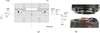 |
Fig. 18 The double-layer hydrostatic forming experiment (a) A schematic view of designed die (b) The experimental setup. |
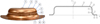 |
Fig. 19 The measuring points. |
3.2.2 Experimental scheme design
This section presents the hydrostatic forming experiments for two cases: Cu/DC04 (DC04 as the outer layer) and DC04/Cu (Cu as the outer layer). In these setups, the inner layer made direct contact with the fluid, while the outer layer was in contact with the hydrostatic die which was lubricated with a polymer layer to achieve a friction coefficient of 0.1 [25]. Based on the simulation results from the previous section, a forming pressure of 42 MPa was selected, as it provided favorable conditions for drawing the blank into the die cavity while avoiding wrinkling at the edge of the product. The thickness measurements at various points under this forming pressure are shown on Figure 20.
Figure 20 indicates that the Cu layer in the DC04/Cu case experienced more significant thinning compared to the Cu/DC04 case. In both scenarios, the most substantial thinning occurred at the bottom corner radius, identified as Position 3. These results closely matched the simulation findings described earlier. The maximum thinning measured 0.345 mm in the DC04/Cu case and 0.355 mm in the Cu/DC04 case.
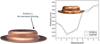 |
Fig. 20 Experimental results of thickness of the target sheet Cu. |
3.2.3 Simulation accuracy verification
To assess the accuracy of the numerical simulation, the wall thickness of the Cu layer from the simulation was compared with the experimental results. Figures 21a,21b shows the comparisons for both cases. In each case, the bottom radius (Position 3) was where the minimum wall thickness of the Cu layer was found. The simulation accuracy reached 97.95% for the Cu/DC04 case and 99.71% for the DC04/Cu case. The simulation results show generally good agreement with the experimental data in terms of overall deformation shape and final cup height. However, certain deviations in thickness were observed. These differences can be attributed, in part, to the assumption of isotropic plastic behavior in the numerical model since rolled sheets often exhibit anisotropic plastic properties.
 |
Fig. 21 The comparisons of simulation results with experiment results (a) Cu/ DC04 case (b) DC04/Cu case. |
4 Conclusions
This study investigated the formability characteristics of double-layer Cu/DC04 sheets. The constitutive model was implemented in the ABAQUS software to simulate the hydrostatic forming of the double-layer sheets, with experiments conducted to verify the accuracy of the simulations. The key findings are summarized as follows:
Comparing the hydrostatic forming results of single-layer sheets with those of double-layer sheets showed that the presence of the outer DC04 layer improved the overall uniformity of thickness distribution across the plate. This enhancement led to greater uniformity in the wall thickness of the Cu target parts and a reduction in the maximum thinning rate of the Cu component.
An equation describing the relationship between the hydroforming fluid pressure (P) and the maximum thinning (y) of the target Cu sheet during the two stages was established. This equation enables straightforward calculation of the maximum thinning under the specified conditions.
The experimental results were generally consistent with the wall thickness values obtained from numerical simulations, achieving a simulation accuracy of 97.95% for the Cu/DC04 case and 99.71% for the DC04/Cu case.
Acknowledgments
This research was funded by Hanoi University of Science and Technology (HUST) under project number T2023-PC-006.
Funding
This research was funded by Hanoi University of Science and Technology (HUST) under project number T2023-PC-006.
Conflicts of interest
On behalf of all authors, the corresponding author states that there is no conflict of interest.
Data availability statement
Data openly available in a public repository.
Author contribution statement
Author Minh-Quan Nguyen: Analyzing experimental data; Participate in designing experimental system.
Author Nguyen Hoang Duong: Design and manufacture a complete test system, Writing − original draft.
Author Thu Nguyen Thi: Writing − review and editing, Methodology.
References
- F.A. Marandi, A.H. Jabbari, M. Sedighi, R. Hashemi, An experimental, analytical, and numerical investigation of hydraulic bulge test in two-layer Al-Cu sheets, J. Manuf. Sci. Eng. 139 (2017) 10 [Google Scholar]
- J.J. Homan, Fatigue initiation in fibre metal laminates, Int. J. Fatigue 28 (2006) 366–374 [Google Scholar]
- H.-C. Tseng, C. Hung, C.-C. Huang, An analysis of the formability of aluminum/copper clad metals with different thicknesses by the finite element method and experiment, Int. J. Adv. Manuf. Technol. 49 (2010) 1029–1036 [Google Scholar]
- R. Zafar, L. Lihui, R. Zhang, Analysis of hydro-mechanical deep drawing and the effects of cavity pressure on quality of simultaneously formed three-layer Al alloy parts, Int. J. Adv. Manuf. Technol. 80 (2015). https://doi.org/10.1007/s00170-015-7142-y [Google Scholar]
- R.-j. Zhang, L.-H. Lang, R. Zafar, K. Li, L. Wu, Effect of gap generator blank thickness on formability in multilayer stamp forming process, Trans. Nonferrous Metals Soc. China 26 (2016) 2442–2448 [Google Scholar]
- S. Kalyanasundaram, S. Dhar Malingam, S. Venkatesan, A. Sexton, Effect of process parameters during forming of self-reinforced − PP based fiber metal laminate, Compos. Struct. 97 (2013) 332–337 [Google Scholar]
- T. Sinmazçelik, E. Avcu, M.Ö. Bora, O. Çoban, A review: fibre metal laminates, background, bonding types and applied test methods, Mater. Des. 32 (2011) 3671–3685 [Google Scholar]
- J.G. Carrillo, W.J. Cantwell, Mechanical properties of a novel fiber-metal laminate based on a polypropylene composite, Mech. Mater. 41 (2009) 828–838 [Google Scholar]
- M.R. Morovvati, A. Fatemi, M. Sadighi, Experimental and finite element investigation on wrinkling of circular single layer and two-layer sheet metals in deep drawing process, Int. J. Adv. Manuf. Technol. 54 (2011) 113–121 [Google Scholar]
- M. Nourjani Pourmoghadam, R. Shahrokh Esfahani, M.R. Morovvati, B. Nekooei Rizi, Bifurcation analysis of plastic wrinkling formation for anisotropic laminated sheets (AA2024-Polyamide-AA2024), Comput. Mater. Sci. 77 (2013) 35–43 [Google Scholar]
- M. Fazlollahi, M. Morovvati, B. Dariani, Theoretical, numerical and experimental investigation of hydro-mechanical deep drawing of steel/polymer/steel sandwich sheets, Proc. Inst. Mech. Eng. Part B: J. Eng. Manuf. 233 (2018) 095440541878017 [Google Scholar]
- M.R. Saeedi, M.R. Morovvati, B. Mollaei-Dariani, Experimental and numerical investigation of impact resistance of aluminum-copper cladded sheets using an energy-based damage model, J. Braz. Soc. Mech. Sci. Eng. 42 (2020) 310 [Google Scholar]
- Y. Wang, L.-H. Lang, T.-J. Gao, Q.-D. Zhang, Flow property of AA2B06 sheet using overlapping elliptical bulge test, Trans. Nonferrous Metals Soc. China 26 (2016) 2179–2187 [Google Scholar]
- W. Liu, Y.-Z. Chen, L. Hu, Z.-C. Zhang, Deformation of large curved shells using double-sided pressure sheet hydroforming process, Int. J. Lightweight Mater. Manuf. 5 (2022) 397–410 [Google Scholar]
- A. Aghchai, M. Shakeri, B. Mollaei-Dariani, Theoretical and experimental formability study of two-layer metallic sheet (Al1100/St12), Proc. Inst. Mech. Eng. Part B: J. Eng. Manuf. 222 (2008) 1131–1138 [Google Scholar]
- A. Marques, P. Prates, A. Pereira, N. Sakharova, M. Oliveira, J. Fernandes, Numerical study on the forming behaviour of multilayer sheets, Metals 10 (2020) 716 [Google Scholar]
- X. Yue, J. Wang, X. Li, L. You, H. Ru, Microstructures and mechanical properties of a two-layer B4C/Al-B4C/TiB2 composite, Mater. Sci. Eng. A 559 (2013) 719–724 [Google Scholar]
- T. Sakaki, K. Kakehi, Y. Ohtakara, Plastic anisotropy of clad sheets, Int. J. Plast. 7 (1991) 505–527 [Google Scholar]
- T.A.K.S. Mori, Press-formability of stainless steel and aluminum clad sheet, J. Mater. Process. Technol. 55 (1996). https://api.semanticscholar.org/CorpusID:135684254 [Google Scholar]
- H.D. Manesh, A.K. Taheri, Theoretical and experimental investigation of cold rolling of tri-layer strip, J. Mater. Process. Technol. 166 (2005) 163–172 [Google Scholar]
- L. Lang, J. Danckert, K.B. Nielsen, Multi-layer sheet hydroforming: experimental and numerical investigation into the very thin layer in the middle, J. Mater. Process. Technol. 170 (2005) 524–535 [Google Scholar]
- K. Pazand, A. Moarrefzadeh, M.R. Morovvati, Experimental and numerical evaluation of formability in three-layer metallic sheets with various layer arrangements, Eng. Res. Express 4 (2022). https://doi.org/10.1088/2631-8695/ac89ce [Google Scholar]
- X.J. Liu, Z.H. Zhang, X.F. Ma, C. Li, Y.Y. Zhou, Study on hydroforming of AA6061-T6 aluminum alloy sheet based on upper sheet, Int. J. Adv. Manuf. Technol. 123 (2022) 4447–4464 [Google Scholar]
- A.Y. Nourouzi, M. Bakhshi JooyPai, H. Gorji, Experimental study of drawing load curves in forming conical parts by hydroforming and conventional deep drawing processes, Adv. Mater. Res. (2011) 556 –560. https://doi.org/10.4028/www.scientific.net/AMR.291-294.556 [Google Scholar]
- P.L. Menezes, Kishore, S.V. Kailas, M.R. Lovell, Friction and transfer layer formation in polymer-steel tribo-system: role of surface texture and roughness parameters, Wear 271 (2011) 2213–2221 [Google Scholar]
Cite this article as: Minh-Quan Nguyen, Nguyen Hoang Duong, Thu Nguyen Thi, Effect of fluid pressure on the thickness distribution of single-layer and double-layer cups, Manufacturing Rev. 12, 23 (2025), https://doi.org/10.1051/mfreview/2025018
All Tables
All Figures
|
Fig. 1 Schematic of double-layer sheet in hydrostatic forming. |
| In the text | |
|
Fig. 2 The uniaxial tensile test: (a) Tensile specimens, (b) MTS testing machine. |
| In the text | |
|
Fig. 3 Stress-plastic strain curves. |
| In the text | |
|
Fig. 4 The specific part size. |
| In the text | |
|
Fig. 5 The finite element model of double-layer sheet in hydrostatic forming. |
| In the text | |
|
Fig. 6 Path of nodes. |
| In the text | |
|
Fig. 7 Cu layer in DC04/Cu case (a) 42 MPa (b) Exceeding 42 MPa. |
| In the text | |
|
Fig. 8 Cu layer in Cu/DC04 case (a) 48 MPa (b) Exceeding 48 MPa. |
| In the text | |
|
Fig. 9 Wall thickness distribution of target Cu sheet at 42 MPa. |
| In the text | |
|
Fig. 10 Wall thickness distribution of Cu layer in the free bulging stage (a) single-layer (b) double −layer. |
| In the text | |
|
Fig. 11 Wall thickness distribution of Cu layer in the finishing stage: (a) single-layer and (b) double −layer. |
| In the text | |
|
Fig. 12 The formed copper Cu thickness comparison (a) Free bulging stage (b) Finishing stage. |
| In the text | |
|
Fig. 13 The target part Cu contour under different hydraulic pressures. |
| In the text | |
|
Fig. 14 The target Cu sheet thickness distribution under different hydraulic pressures. |
| In the text | |
|
Fig. 15 Wall thickness distribution (a) 8 MPa (b) 10 MPa (c) 30 MPa (b) 40 MPa. |
| In the text | |
|
Fig. 16 Pressure-maximum thinning in bulging stage of Cu layer. |
| In the text | |
|
Fig. 17 Pressure-maximum thinning in finishing stage of Cu layer. |
| In the text | |
|
Fig. 18 The double-layer hydrostatic forming experiment (a) A schematic view of designed die (b) The experimental setup. |
| In the text | |
|
Fig. 19 The measuring points. |
| In the text | |
|
Fig. 20 Experimental results of thickness of the target sheet Cu. |
| In the text | |
|
Fig. 21 The comparisons of simulation results with experiment results (a) Cu/ DC04 case (b) DC04/Cu case. |
| In the text | |
Current usage metrics show cumulative count of Article Views (full-text article views including HTML views, PDF and ePub downloads, according to the available data) and Abstracts Views on Vision4Press platform.
Data correspond to usage on the plateform after 2015. The current usage metrics is available 48-96 hours after online publication and is updated daily on week days.
Initial download of the metrics may take a while.