| Issue |
Manufacturing Rev.
Volume 12, 2025
Advanced Manufacturing Research – Latest Developments
|
|
|---|---|---|
| Article Number | 13 | |
| Number of page(s) | 23 | |
| DOI | https://doi.org/10.1051/mfreview/2025004 | |
| Published online | 05 May 2025 | |
Original Article
Experimental study of a novel contact-based pose detection approach for digital twin-driven high-precision micro assembly
1
School of Engineering and Physical Sciences, Heriot-Watt University, Edinburgh EH14 4AS, UK
2
School of Mathematical and Computer Sciences, Heriot-Watt University, Edinburgh EH14 4AS, UK
* e-mail: This email address is being protected from spambots. You need JavaScript enabled to view it.
Received:
14
November
2024
Accepted:
1
March
2025
Abstract
This study presents a comprehensive study of a novel Contact-Based Pose Estimation Method (CBPEM) for enhancing precision in robotic assembly processes within digital twin frameworks. Conventional pose detection methods, such as laser and computer vision-based point cloud acquisition, are often hindered by limitations related to optical properties and occlusion when detecting small or intricate components. In contrast, CBPEM leverages contact-based detection using capacitive or load cell sensors, offering a high degree of position and orientation accuracy while mitigating the optical challenges posed by traditional methods. This study focuses on the precision assembly of a concentrator photovoltaic solar unit, which consists of primary and secondary lenses, a solar cell, and a tripod leg their small size, deformability, and unique optical properties, making pose estimation particularly challenging. Experimental evaluations were conducted to compare the effectiveness of capacitive and load cell sensors in detecting contact points, assessing their precision and accuracy on flexible and rigid components. CBPEM demonstrated commendable performance with position accuracies reaching 0.05 mm and orientation accuracies around 0.4 degrees, matching or surpassing traditional optical methods. While CBPEM provides enhanced accuracy, it requires sequential data acquisition, resulting in lower detection speeds compared to optical methods. Additionally, the method’s efficacy depends on the precision of robotic components and may be impacted by complex geometries or highly deformable surfaces. Overall, CBPEM offers a robust alternative for precision pose estimation in digital twin-driven robotic assembly, particularly when dealing with components unsuited to optical methods. Future research should explore hybrid approaches to optimize detection speed and adaptability across a broader range of robotic assembly scenarios.
Key words: Contact-based pose estimation / digital twin / robotic assembly / capacitive sensor / load cell
© B. Nazeer et al., Published by EDP Sciences 2025
 This is an Open Access article distributed under the terms of the Creative Commons Attribution License (https://creativecommons.org/licenses/by/4.0), which permits unrestricted use, distribution, and reproduction in any medium, provided the original work is properly cited.
1 Introduction
The Digital twin (DT) technology, which involves the creation of virtual replicas of physical systems, has garnered significant attention in the field of robotics [1], particularly for precision assembly applications involving small components. By providing a real-time, data-driven simulation environment, digital twins enable improved monitoring, control, and optimization of assembly processes. Multiple studies highlight the effectiveness of digital twins in simulating and refining robotic operations for precision tasks. This research is the part of smart assembly project that aims to optimize the precision of the robotic assembly process for small, reflective and transparent components with digital twin.
Similar to the parts of assembly system under study (Fig. 1), most robotic assembly systems use parts made with 3D printing or CNC milling. However, these parts often have slight differences from their original CAD designs after manufacturing. When used in a robot, these differences—such as size and position—can affect the overall design and make it harder to create an accurate digital twin. Most studies create digital twins for robotic assembly systems based only on CAD models and assembly layouts. For example, Burghard et al. [2] explored a new way to program assembly robots using virtual reality (VR) and digital twin technology. Hu et al. [1] suggested that a high-quality Digital Twin (DT) should include detailed information like geometric, physical, and conditional data. The CAD software like UG, AutoCAD, SolidWorks, and Creo can display these geometric properties well, but the actual manufactured parts often have differences that CAD models cannot fully capture and tracking these details for all parts in an assembly is difficult, especially since they can change over time. This makes them unreliable for building accurate digital twins.
Mo et al. [3] highlighted similar challenges, noting that digital twins often fail to represent the real physical and geometric properties of robots and their environments. They proposed a smart digital twin framework that collects detailed sensor data to improve the robot’s understanding of its surroundings. Other researchers have included point cloud data in digital twins. For instance, Sun et al. [4] used high-precision laser scanners to compare actual parts with their ideal models. Wang et al. [5] introduced a Part Digital Twin Model (PDTM) that improved assembly accuracy by combining CAD models, point clouds, and mesh models. They also used laser-based point cloud scanning to automate part positioning and improve assembly efficiency.
Despite these advancements, combining data from different sensors (such as cameras, LiDAR, and ultrasonic sensors) is complex and may cause inconsistencies. Processing large amounts of data in real-time requires significant computing power and advanced algorithms, which can be costly and impractical for some applications.
Pose estimation, which determines the position and orientation of parts, has been widely researched. Previous studies [1] have used computer vision and depth information for this task. For example, PoseCNN [6] is a deep-learning method for estimating 6D poses in cluttered environments. Su et al. [7] improved this by integrating semantic segmentation with pose estimation. Bousmalis et al. [8] developed a model that directly predicts 3D object positions, while Garbade et al. worked on real-time pose estimation for robotic arms [9]. Tremblay et al. [10] also proposed a deep-learning approach to pose estimation.
For precise assembly of small, intricate parts, extremely tight tolerances are required—within sub-millimeter ranges and orientation tolerances as small as 0.5 degrees for assembly objects and fixtures. In such systems, it is crucial to evaluate how well proposed models can accurately capture spatial, geometric, and pose data. For example, Kim et al. [11] found that the accuracy of the Part Digital Twin Model (PDTM) can reach 2.5 mm for position detection and 0.4 degrees for orientation, while its precision is 0.3 mm for position and 0.1 degrees for orientation.
This study focuses on the precision assembly of a concentrator photovoltaic solar unit provided by Chitendai Ltd., which consists of primary and secondary lenses, a solar cell, and a tripod leg (Fig. 2). The solar cell (18 mm × 12 mm) and the flexible hexapod frame were chosen for detailed analysis due to their small size, deformability, and unique optical properties, making pose estimation particularly challenging. Traditional vision- and laser-based methods struggle with such components due to occlusion, reflections, and translucency, affecting their accuracy in robotic assembly [12].
In addition, robotic assembly systems, similar to the setup studied in this research, frequently incorporate strain gauge-based force sensors, such as load cells, to monitor assembly forces [14]. These sensors are typically positioned either between assembly components and a fixed base or between the gripper and the robot [15]. However, during our experiments, it was observed that strain gauge-based force sensors exhibit minor plastic deformation under repeated, unidirectional force application, a common condition in robotic assembly [16]. Such minor plastic deformations accumulate with repeated assemblies, potentially altering the geometrical and physical properties of setup components, such as the spatial position of fixtures (Fig. 1).
To address these limitations, this study proposes a contact-based pose estimation method (CBPEM) [17], achieving 0.5-degree orientation accuracy and 1 mm linear pose accuracy for small components such as the solar cell unit (Fig. 2). Initially, the method relied on load cell-based force sensing to detect contact between components, but it was later enhanced with a capacitance-based detection technique, which is particularly useful for objects that induce capacitance drops upon contact. Capacitive tactile sensors improve robotic perception by detecting capacitance changes when objects interact, allowing for precise detection and control.
Beyond pose estimation, capacitive sensors play a crucial role in human-robot interaction (HRI) and metal detection. These sensors can detect human proximity, ensuring safer robot operation [18]. A robotic cage was equipped with capacitive antennas that sensed human presence when capacitance changes were detected in the workspace. Compared to other sensor types, capacitive sensors are simpler to implement, as they require only a metal foil or mesh attached to the robot’s surface to act as an electrode [19]. Additionally, capacitive sensors are effective in detecting metal debris in industrial applications, such as monitoring lubricating oil [20].
The study highlights the importance of accurate and repeatable pose detection in robotic assembly systems to improve digital twin modeling and process optimization. Components within the assembly, particularly small and flexible ones, may assume different poses each time they are picked up or placed. By integrating contact-based sensing techniques, this research enhances the reliability and efficiency of robotic assembly, overcoming the limitations of vision-based methods [7,10,12].
This method precisely reconstructs the 6D pose of physical components—including fixtures, robots, and assembly objects—within the digital twin. It helps correct geometric and spatial inaccuracies that occur during manufacturing and assembly, ensuring a more accurate virtual representation of the system.
 |
Fig. 1 Exploded view of fixture assembly mounted on PI Hexa-pod. |
 |
Fig. 2 Assembly components − 1: Tripod-leg, 2: Solar cell, 3: Secondary lens, 4: Primary lens, 5: Complete assembly. |
2 Materials and methods
The current assembly system configuration (Fig. 3b) incorporates a Meca500 6-axis industrial robot arm with the precision of .005 mm for manipulating assembly components and determining the 6D pose of system components using the Contact-Based Pose Estimation Method (CBPEM). Additionally, an H-811.I2 6-Axis Miniature Hexapod (Fig. 1) with high precision of .001mm enables precise 6D pose adjustments of the primary assembly fixture based on data acquired from the CBPEM, hexapod was also critical for the accuracy and precision analysis of CBPEM as the high accuracy of hexapod was leveraged to introduce the known deviations in the pose of assembly component to study the CBPEM. A 3-axis force monitoring load cell is installed between the hexapod and the fixture assembly (Fig. 3d), allowing for precise force monitoring down to 0.001 Nm on the tripod frame (Fig. 2) mounted on the fixture. This load cell can detect the contact force applied by the Meca500 gripper on various surfaces on the fixture and even on the tripod frame that will be mounted on the fixture. Contact detection is achieved by monitoring force changes on the fixture assembly, enabling the CBPEM to determine the 6D pose of the fixture assembly, tripod frame, and solar cell. This pose data is then used to accurately position 3D models of these components within the virtual environment, ensuring precise alignment during assembly. The contact detection is enhanced by using a capacitive touch sensors, integrated in the assembly on gripper tips (Fig. 3c) and fixture contact plate (Fig. 3e), using copper foil as the electrode, allowing detection along two axes. Copper foil is particularly advantageous due to its thinness (<0.1 mm), which allows it to hold the shape of the gripper structure. The MPR121 breakout board is used to connect capacitive touch electrode with Arduino board via I2C communication. Capacitive sensors provide fast, accurate contact detections, making them suitable for handling lightweight metal objects that may not be reliably detected by force sensors.
The assembly and pose estimation processes, facilitated by CBPEM, are coordinated and monitored through a digital twin of the assembly setup (Fig. 3a). The tests in this study were orchestrated by means of the digital twin. This digital twin is developed from the ground up in Unity 3D to create the virtual environment, utilizing C# and C++ for software development. CAD files are used to roughly position static assembly components, such as fixtures, while Unified Robot Description Format (URDF) files are employed to import dynamic components, such as robots, to define precise poses and joint parameters in the virtual environment. The digital twin communicates with the Meca500 robot and hexapod through TCP/IP protocols, while a UART interface links it to a microcontroller board that interfaces with sensors and fixture jaw actuation motors. Additionally, a ROS (Robot Operating System) interface is implemented, providing flexibility for future integration with other robots and sensors.
 |
Fig. 3 Assembly system layout with individual component. |
2.1 CBPEM for system and assembly components
The CBPEM can accurately determine the 6D pose of an object in the assembly workspace.
The CBPEM initiates by moving the gripper towards the component from a predefined position, accounting for the component’s positional tolerance. The position of leading contact face of gripper is always known from the digital twin, when the leading contact face of the gripper contacts the object, the gripper’s movement halts (Fig. 5).
When the gripper makes the contact, the position of the gripper leading contact face is recorded to locate the contacted face or edge of the object in coordinate form (x,y) where x is the point on the axis along witch the gripper was moving while y is the position of point on axis along which further readings will be recorded.
The contact points of the object are predefined and there ideal position is known by the robot there actual position is determined after contact, contact point are defined in a way that if the contact point lies on a flat plane of the object then the gripper front edge should contact or if the contact point lies on an flat edge of object, gripper front edge can contact if its perpendicular, or else side plane can contact depending on the dexterity of robot.
The leading contact face of a robot gripper is the first surface of the gripper that makes physical contact with an object as the gripper moves in a particular direction toward that object, this surface is always perpendicular to the axis of gripper motion. This face depends on the motion direction of the gripper relative to the object. If the gripper is moving forward toward an object in front, the front edge of the gripper is the leading contact face, in this case the contact will be a line contact with object face or point contact with the perpendicular object edge, if the gripper is moving left the left face of the gripper is the leading contact face, the contact will be a line contact with object edge.
If a line contact is made the center point of the gripper face or edge is taken as contact point, as the offset between actual contact point on edge or plane of gripper with object edge or plane, in the direction of movement, will be constant for all the contact with that perticular edge or plane for same direction of movement.
By repeating this process for multiple edges and faces of the object (Fig. 4), these planer contact positions ((x,y) coordinates for multiple points) can be combined to reconstruct the 6D pose of the component accurately. Additionally, the global coordinate system for the assembly setup (Fig. 3a) is based on Unity3D’s coordinate system, simplifying integration and alignment within the digital twin.
 |
Fig. 4 Contact points for CBPEM for tripod frame. |
 |
Fig. 5 First contact point for frame and all the contact points on fixture surface. |
2.1.1 CBPEM for tripod frame
To determine the orientation (RP) of the tripod frame about the Y-axis (Fig. 4d) (The coordinates are defined based on the ideal position with respect to assembly setup), the coordinates (a, b) and (x, y) can be identified (Fig. 4b), as these are contacted by grippers front edge. These coordinates are recorded when the gripper edge contacts the frame’s edges (Fig. 5b).
As the gripper moves along the Z-axis, contact with the frame’s left edge provides the coordinates (a, b) (Fig. 5b), and contact with the frame’s right edge provides (x, y) (Fig. 5b), the ideal position of these frame edges on all three axis are known and can be use to position the gripper to touch the front edge as long as the positive or negative deviation along X axis is under the half-length of gripper front edge. Using these recorded coordinates, the angle θy (rotation about the Y-axis) is calculated (Fig. 4b) using equation (1).
 (1)
(1)
Similarly, to determine the RP θx about the X-axis, the gripper moves along the Z-axis, griper front edge making contact with the frame top edge to establish coordinates (x, y) and with the bottom edge to establish coordinates (a, b) (Fig. 4c). To determine RP θz about the Z-axis, the gripper moves along the X-axis, contacting the top edge of frame with right face of gripper to identify (a, b) and the bottom edge to identify (x, y) (Fig. 4a).
The process of acquiring coordinates for six points for CBPEM (two points along each axis which gives the rotation about that axis) across two perpendicular planes (These are the planes perpendicular to the direction of motion of gripper hence plane (x,y) along Z axis and (z,y) along X axis) to determine the 6D pose of the frame is similarly applied to the pose estimation of the fixture assembly. Specifically, contact points Y1 and Y2 (Fig. 5c) are used to determine the orientation of the fixture about the Y-axis, points Z1 and Z2 establish the orientation about the Z-axis, and points X1 and X2 define the orientation about the X-axis (As per world coordinate system (Fig. 3a).
2.1.2 CBPEM for solar cell
Similar to the pose detection of the frame, the proposed method can be applied to precisely detect the 6D pose of smaller assembly components. While the frame stay mounted on the fixture for rest of the assembly, the pose estimation of frame is done by detecting the contact between frame and gripper, however this is not possible in the case of solar cell as the pose of the solar cell is critical after the pickup (when cell is in gripper). The CBPED approach used for frame cannot be used for solar cell to determine its pose. Hence while the solar cell is within the gripper, the pose estimation is performed by detecting the contact between solar cell and frame fixture. As the pose of fixture is determined beforehand. Unlike the frame, the translation of the solar cell along the Y-axis (Fig. 6a) and its rotations about the X- and Z-axes are constrained by the gripper (Fig. 6b), which simplifies pose estimation. In this case, pose determination involves identifying translations along the X- and Z-axes and rotation about the Y-axis (The coordinates are defined based on the ideal position with respect to assembly setup). The translation of the solar cell along the Z-axis can be established by detecting contact between the front circumferential edge of the cell (Fig. 7c) and the fixture’s contact surface (Fig. 3e) along the Z-axis. To determine the rotation about the Y-axis, the coordinates (a, b) and (x, y) are obtained along the edge of the cell (Fig. 7b) by detecting contact between the cell’s edge and the fixture contact surface edge (Fig. 3e) along the X-axis. These contact points also enable the determination of translation along the X-axis (Fig. 7a).
 |
Fig. 6 Solar cell pose in gripper and coordinate definition. |
 |
Fig. 7 Contact points for CBPEM for solar cell. |
3 Results
3.1 Results for CBPEM for Solar Cell using force monitoring for contact detection
The solar cell was initially picked up from a fixture mounted on a hexapod, and its pose was determined using CBPEM (Detected orientation) where contact was detected using force data from contact points Tables 1 and 2. This initial orientation value was recorded as the “initial orientation”. The cell was then repositioned on the hexapod fixture, and a known rotational deviation about the Y-axis was introduced via the hexapod; this deviation is referred to as the “new orientation”. CBPEM was subsequently used to measure the “Determined orientation” by subtracting the newly detected orientation (Detected orientation) from the initial orientation. This process was done to monitor how closely CBPEM can measure the deviations introduced by hexapod (Figs. 8 and 9).
Data from CBPEM for Solar cell. This Table shows the data for range −10 to 0 degrees of new orientation.
Data from CBPEM for Solar cell. This table shows the data for range 0 to 10 degrees of new orientation.
 |
Fig. 8 Induced and Determined orientation for range −10 to 0. |
 |
Fig. 9 Induced and Determined orientation for range 0 to 10. |
3.2 Accuracy and Precision study for contact detection methods for CBPEM
To evaluate the viability of CBPEM relative to alternative methods [1], it is essential to examine whether its accuracy and precision are comparable with established methods, such as laser-based point cloud acquisition or computer vision (CV)-based pose estimation. Given that CBPEM is proposed for use with unconventional objects like the tripod frame, it may encounter specific challenges associated with pose detection. One notable challenge involves the deformation of flexible objects upon contact, which can introduce significant errors in identifying accurate contact points. Thus, a detailed study is needed to assess CBPEM’s performance across objects with varying physical and geometric properties. A study was conducted on the material properties of the tripod frame using Finite Element Method (FEM)-based deformation analysis in Autodesk Fusion 360 software. The findings revealed that the frame’s edge, utilized to detect the pose about the Y-axis (Figs. 4b and 5b), is the most flexible part of the entire assembly. Under an applied force of 0.001 Nm, this edge exhibited a deformation of 0.05 mm. This finding is particularly significant because 0.001 Nm (Fig. 10) corresponds to the activation threshold or least count for the load cells used to detect contact between the gripper and the frame edge. Consequently, when using load cell-based contact detection methods for flexible components like the tripod frame, contact cannot be detected without inducing some deformation in the component’s surface. It is therefore essential to examine the implications of this deformation on the performance and accuracy of CBPEM, particularly when applied to objects with flexible structures.
For this analysis, two objects—the tripod frame and the assembly fixture—are compared across multiple parameters, including contact detection accuracy and precision, as well as pose detection accuracy and precision. The tripod frame presents challenges related to its flexible characteristics, while the assembly fixture exhibits significant deviations from the ideal pose, providing a basis for evaluating CBPEM’s robustness under different conditions.
Additionally, as discussed, CBPEM can employ either capacitance-based or force-based contact detection methods. However, certain objects may not be suitable for capacitance-based contact detection due to their material properties, as observed with primary and secondary lenses in the studied assembly (Fig. 2), therefore it is crucial to compare the accuracy and precision of CBPEM when using each contact detection method to determine its effectiveness across diverse materials. An initial experimental study was conducted to examine the behavior of the sensors as the gripper made contact with both of the studied objects: the frame (Fig. 11) and the fixture (Fig. 12). Raw data from both onboard sensors were collected in real-time while the gripper approached the predefined contact points on the assembly and system components. The data is presented without conversion into their respective units, such as force and capacitance. It can be observed that capacitance drop upon the contact is similar for frame (Fig. 11) and fixture (Fig. 12), however the change in detected force is gradual for frame as gripper moves inwards (Fig. 11) toward the frame while for fixture the change in detected force is relatively instantaneous (Fig. 12).
 |
Fig. 10 Deformation in frame edge upon contact. |
 |
Fig. 11 Frame contact detection, left vertical axis load cell data, right vertical axis capacitance drop data, horizontal axis gripper tip position on Z axis in meters. |
 |
Fig. 12 Fixture contact detection, left vertical axis load cell data, right vertical axis capacitance drop data, horizontal axis gripper tip position on Z axis in meters. |
3.2.1 Accuracy and precision study of contact detection methods for CBPEM applied to the tripod frame
To evaluate the accuracy and precision of contact detection methods for the tripod frame within the CBPEM framework, a controlled study was carried out using both load cell-based and capacitance-based contact detection methods independently. In this study, an ideal stopping point for the gripper upon contacting the frame was first manually established using a high-precision deflection gauge (.01mm); the coordinates at this stopping point were treated as the ideal contact detection point.
Each contact detection method underwent up to 100 test cycles, allowing for a comprehensive analysis of the deviations between the actual stopping points and the ideal stopping point across multiple trials. This data enabled a comparison of the effectiveness of each method in achieving consistent and accurate contact detection, providing insights into which method offers greater reliability and precision for CBPEM applications.
Figure 13 illustrates the graph depicting the relationship between the ideal contact point and the detected contact points over 100 repeated cycles when the force-based contact detection method is used. This graph provides a visual comparison of the deviations from the ideal point, highlighting the consistency and variability of the force-based method in detecting contact with the tripod frame across multiple trials.
The accuracy of the process can be evaluated by calculating the Mean Absolute Error (MAE) between the ideal and measured values. This is represented as follows:
 (2)
(2)
where, n is total number of readings, i is index of summation, xi measured value at i index and ideali is the ideal value.
Substituting values gives MAE =.000603 m or .603 mm.
Thus, the accuracy of contact detection for frame using force based contact detection is .603 mm.
The precision of the process is assessed using the Standard Deviation of the measured values [13]. Standard deviation measures the consistency of the readings, indicating how closely grouped the measurements are around the mean. The standard deviation σ is calculated as:
 (3)
(3)
where n is total number of readings, i is index of summation, xi is measured value at i index and x̄ is sample mean of values.
 (4)
(4)
Using the measured values:
σ = 8.46×10⁻⁵ m or 0.085mm.
Thus, the precision of contact detection for frame using force-based contact detection is 0.085 mm.
The digital twin was used to visualize the accuracy of contact detection using real-time force data feedback (Fig. 14). By overlaying the sensor feedback onto the digital model, the system enabled a precise visualization of the gripper tip’s interference with the frame edge. This setup also illustrated the difference between the ideal stopping marker and the actual stopping point, providing a clear visual assessment of contact point accuracy.
Figure 15 shows the graph between ideal contact point and detected points for 100 repeated cycles when the contact point is detected using capacitance drop based contact detection.
By calculating precision and accuracy values in a similar manner as described, the precision for contact detection of the frame’s edge using capacitance drop-based contact detection was determined to be 0.0444 mm, with an accuracy of 0.0949 mm. This accuracy value was then visualized within the digital twin environment (Fig. 14), allowing for a detailed view of the contact detection accuracy and its deviation from the ideal contact point.
 |
Fig. 13 Ideal and Actual contact points when contact is determined using force feedback, in meters. Position of contact point on the axis parallel to the motion of gripper on vertical axis. |
 |
Fig. 14 Contact detection visualization in digital twin. |
 |
Fig. 15 Ideal and Actual contact points when contact is determined using capacitance drop, in meters. Position of contact point on the axis parallel to the motion of gripper on vertical axis. |
3.2.2 Accuracy and precision study for contact detection methods for CBPEM for fixture assembly
To evaluate the accuracy and precision of contact detection for the fixture’s contact surface (Figs. 1 and 3e), a controlled study was conducted using both cell-based and capacitance-based contact detection methods independently. As in previous studies, an ideal stopping point for the gripper upon contact with the fixture was manually established using a high-precision deflection gauge (.01 mm), with the coordinates at this point recorded as the ideal contact detection location. Each contact detection method was tested over 100 cycles.
Figure 16 displays a graph that compares the ideal contact point with the detected contact points over 100 repeated cycles when using force-based contact detection. In this graph, the ideal contact point is represented as a constant reference line, while the detected contact points vary per cycle, illustrating the differences between the actual and ideal stopping positions. This visualization provides insight into the accuracy and repeatability of force-based contact detection for the fixture’s contact surface.
Using the same method of calculation as in previous analyses, the precision for contact detection of the fixture’s contact surface with load cell-based detection was found to be 0.096 mm, while the accuracy was determined to be 0.263 mm. Figure 17 presents a graph comparing the ideal contact point with the detected contact points across 100 repeated cycles when using capacitance drop-based contact detection. The ideal contact point is shown as a reference line, with each cycle’s detected contact points plotted to reveal the variation around this ideal.
Using the same method of calculation as in previous analyses, the precision for contact detection of the fixture’s contact surface with capacitance drop-based detection was found to be 0.196 mm, while the accuracy was determined to be 0.322 mm. These values quantify the precision and accuracy of the capacitance drop-based method in detecting contact points on the fixture’s surface, indicating the level of reliability and consistency of this detection method.
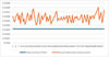 |
Fig. 16 Ideal and Actual contact points when contact is determined using force feedback in meters. |
 |
Fig. 17 Ideal and Actual contact points when contact is determined using capacitance in meters. |
3.2.3 Accuracy and precision study for pose detection methods for CBPEM for tripod frame
The accuracy and precision study of contact detection for the tripod frame offers important insights into the effectiveness of CBPEM. However, it is essential to evaluate how the accuracy and precision of contact detection translate into the accuracy and precision of the detected orientation. To address this, similar tests were conducted to capture the pose of the tripod frame when mounted on the hexapod.
For precision testing, the pose of the frame was repeatedly checked under constant conditions, with no external deviations applied. Contact was detected using force data obtained from load cells (Fig. 18 and Tab. 3), the findings from six instances of detected orientation are included.
Similar data was recorded for the frame’s orientation about all three axes using capacitance drop-based contact detection (Fig. 19 and Tab. 4). It should be noted that for the sake of conciseness, only six instances of each reading have been presented. However, a more extensive study was conducted, and the extended data demonstrated a consistent trend with the instances included in this paper, the findings presented are representative of the overall study.
Based on the results, the calculated precision values for CBPEM pose detection were as follows. For force-based contact detection, the pose detection accuracy about the X-axis was 0.007 degrees, about the Y-axis was 0.015 degrees, and about the Z-axis was 0.24 degrees. In comparison, for capacitance drop-based contact detection, the pose detection precision about the X-axis was 0.008 degrees, about the Y-axis was 0.013 degrees, and about the Z-axis was 0.13 degrees.
For the accuracy test, similar to the load cell accuracy test, known rotational deviations were deliberately introduced to the frame along the Y axis by means of PI-Hexapod, for conciseness of data the values about the Y-axis are presented as this also includes the contact detection along the most deformable edge of the frame (Fig. 10). The pose was subsequently measured to evaluate how effectively CBPEM could detect these deviations. The results for CBPEM, utilizing both load cell-based contact detection and capacitance drop-based contact detection for the frame, are presented (Fig. 20 and Tab. 5).
Using this data to calculate the accuracy of CBPEM for both contact detection methods we get an accuracy of .446 degrees for contact detection with load cell and accuracy of .24 degrees for contact detection with capacitance sensor.
 |
Fig. 18 Orientation of frame about three axes in degrees determined by CBPEM using force-based contact detection, angles in degrees on vertical axis, and instances on horizontal axis. |
Orientation of frame about three axes in degrees determined by CBPEM using force-based contact detection.
 |
Fig. 19 Orientation of frame about three axes in degrees determined by CBPEM using capacitance drop based contact detection, angles in degrees on vertical axis, and instances on horizontal axis. |
Orientation of frame about 3 axis in degrees determined by CBPEM using capacitance-based contact detection.
 |
Fig. 20 Comparison between the induced rotational deviation and the deviation determined by CBPEM during two independent tests. In one test, pose detection was performed using force-based contact detection, while in the other, capacitance drop-based contact detection was employed. Angles in degrees on vertical axis. |
Data from accuracy test of CBPEM for frame.
3.2.4 Accuracy and precision study for pose detection methods for CBPEM for fixture
To evaluate how the accuracy and precision of contact detection translate into the accuracy and precision of the detected orientation, similar tests were conducted to capture the pose of the fixture when assembled on the hexapod. For precision testing, the pose of the fixture was repeatedly checked under constant conditions, with no external deviations applied. Contact was detected using force data obtained from load cells (Fig. 21 and Tab. 6), the findings from six instances of detected orientation are included.
Similar data was recorded for the fixture’s orientation about all three axes using capacitance drop-based contact detection (Fig. 22 and Tab. 7).
For the accuracy test, known orientation deviations were deliberately introduced to the frame, for conciseness of data the values about the Y-axis are presented. The pose was subsequently measured to evaluate how effectively CBPEM could detect these deviations. The results for CBPEM, utilizing both load cell-based contact detection and capacitance drop-based contact detection for the frame, are presented (Fig. 23 and Tab. 8).
Using this data to calculate the accuracy of CBPEM for both contact detection method we get an accuracy of 0.347 degrees for contact detection with load cell and accuracy of 0.298 degrees for contact detection with capacitance sensor.
 |
Fig. 21 Orientation of fixture about three axes in degrees determined by CBPEM using force based contact detection, angles in degrees for X and Z axis on left vertical axis with Y axis pose in degrees on right vertical axis, and instances on horizontal axis. |
Orientation of fixture about three axes in degrees determined by CBPEM using force based contact detection.
 |
Fig. 22 Orientation of fixture about three axes in degrees determined by CBPEM using capacitance drop-based contact detection, angles in degrees for X- and Z- axis on left vertical axis with Y-axis pose in degrees on right vertical axis, and instances on horizontal axis. |
Orientation of fixture about three axes in degrees determined by CBPEM using capacitance-based contact detection.
 |
Fig. 23 Comparison between the induced orientation deviation and the deviation determined by CBPEM during two independent tests. In one test, pose detection was performed using force-based contact detection, while in the other, capacitance drop-based contact detection was employed. Angles are in degrees on vertical axis. |
Data from accuracy test of CBPEM for frame.
4 Discussion
This study assessed the effectiveness of the CBPEM for achieving high-precision pose detection in robotic assembly of small, complex components. CBPEM, particularly when coupled with capacitance-based contact sensors, demonstrated notable accuracy and repeatability in 6D pose detection for components such as solar cells and tripod frames. By addressing spatial deviations and geometric inaccuracies, CBPEM supports the critical requirement of sub-millimeter alignment between physical components and their digital representations in digital twin frameworks. A focal point of the investigation was evaluating the performance of two widely used sensor types — capacitive touch sensors and strain-gauge-based load cells — essential for accurate contact detection between the robotic gripper and component surfaces. Since contact detection underpins CBPEM’s position detection effectiveness, both the precision and accuracy of these sensors were assessed on two different component surfaces: the flexible edge of the tripod frame (Tab. 9) and the rigid, 3D-printed contact surface of the fixture (Tab. 10).
For the flexible tripod frame, capacitance-based contact detection achieved a precision of 0.044 mm and accuracy of 0.0949 mm, outperforming load-cell-based detection, which showed a lower precision of 0.085 mm and a higher error of 0.603 mm (Tab. 9). These results suggest that capacitance sensors, due to their high sensitivity to contact detection, are especially well-suited for applications where flexibility or deformation in components may otherwise affect detection accuracy. The load cell, while reliable for force measurement, showed limitations with flexible components, likely due to slight deformations induced during contact.
For the rigid fixture surface, load cell-based contact detection showed slightly higher precision (0.096 mm) compared to capacitance-based detection (0.196 mm), although capacitance-based detection still provided competitive accuracy of 0.322 mm vs. 0.263 mm for load cell detection (Tab. 10). The minimal difference in performance on rigid surfaces suggests that load cells remain a viable option for components with stable, inflexible geometries. However, the high accuracy observed with capacitance-based detection on both surfaces highlights the potential of this method to provide reliable contact data across a broader range of material properties and configurations, where precision is paramount for alignment within digital twin systems. These findings emphasize CBPEM’s adaptability across varying component types, where high-precision contact detection enables accurate real-time pose adjustments in robotic assembly systems. The advantages of capacitance-based detection, particularly for flexible or deformable materials, suggest future applications where hybrid or sensor-specific configurations could further optimize pose estimation. Moreover, the ability of capacitance sensors to handle subtle contact with high sensitivity provides a promising avenue for enhancing robotic tactile perception for pose detection in settings where maintaining sub-millimeter precision is essential. This study expanded on the CBPEM by evaluating the 6D pose detection accuracy for components like the tripod frame and fixture. While position accuracy along the three axes is directly inferred from the contact detection accuracy, orientation detection requires multiple contact points along different axes and surfaces. This added complexity results in orientation detection accuracy and precision being significantly different from position accuracy and precision, necessitating a separate analysis of orientation performance.
For the tripod frame, the precision of CBPEM when using capacitance-based contact detection about the three axes was as follows: 0.008 degrees about the X-axis, 0.013 degrees about the Y-axis, and 0.13 degrees about the Z-axis. The orientation accuracy about the Y-axis was 0.24 mm (Tab. 11). In comparison, using load cell-based contact detection provided similar precision for the X-axis (0.007 degrees), Y-axis (0.015 degrees) and slightly lower on Z axis (0.24 degrees), but the orientation accuracy about the Y-axis was lower at 0.446 mm. These results suggest that, while both sensor types show comparable precision in detecting orientations, the capacitive-based system provides more consistent results across all axes, making it particularly suitable for scenarios requiring fine orientational adjustments. Furthermore, the lower orientation accuracy with the load cell, especially about the Y-axis, highlights the potential challenges posed by flexible or deformable components, where slight surface deformations may affect the performance of force-based detection systems. For the fixture, the capacitance-based contact detection yielded orientation precisions of 0.063, 0.096, and 0.092 degrees about the X, Y, and Z axes, respectively, with an orientation accuracy of 0.298 mm about the Y-axis (Tab. 12). The load cell-based detection, in contrast, showed less precision about the X and Y axes (0.111 and 0.155 degrees, respectively), but slightly higher about the Z-axis with an orientation precision of 0.022 degrees, and an orientation accuracy of 0.347 mm. For rigid objects the accuracy and precision of pose detection is quite comparable for both the sensors. However, the capacitance sensor’s consistent accuracy across the rotational axes (X, Y, and Z) suggests that it may be better suited for applications requiring uniform precision across multiple directions, particularly when the components involved have more complex geometries or materials that respond better to capacitive touch detection.
When assessing the accuracy of orientation detection for the tripod frame (Fig. 18 and Tab. 5), the measured deflection values obtained from CBPEM using the load cell exhibited a slight lag compared to the actual induced deflection in the frame. In contrast, the measured deflection values from the capacitance-based CBPEM were consistently slightly higher than the actual induced deflections. This difference suggests that each sensor introduces a distinct bias—load cells lag slightly behind actual movement, while capacitance sensors tend to overshoot. Consequently, utilizing both sensors simultaneously could offer a balanced solution, where their respective biases might offset each other. Implementing an averaging algorithm, such as a Kalman filter or Exponential Moving Average (EMA), could capitalize on the strengths of each sensor and reduce individual sensor biases, potentially enhancing pose detection accuracy beyond what each sensor could achieve independently. A Kalman filter, for example, could effectively combine the measurements from both sensors by weighting each based on its estimated variance, thereby smoothing out sensor-specific biases and improving the overall estimate of the pose. Alternatively, an Exponential Moving Average (EMA) could be used to give more weight to recent measurements, allowing for adaptive adjustments to changes in deflection readings while reducing lag or overshoot effects. By applying such algorithms, the combined sensor data could offer higher accuracy and reliability in tracking the orientation, aligning CBPEM’s measurements more closely with real-time deflections.
This study explored the performance of CBPEM for achieving high-precision pose detection in robotic assembly, demonstrating its strengths in position and oritation accuracy. When comparing CBPEM to conventional pose detection methods, such as laser or computer vision (CV)-based point cloud acquisition, which typically achieve a position accuracy of around 2.5 mm and an orientation accuracy of approximately 0.4 degrees [11], CBPEM offers a compelling alternative. Our findings show that CBPEM can achieve position accuracy as high as 0.05 mm and orientation accuracy close to 0.4 degrees, making it a competitive option for precision assembly applications. Unlike laser or CV-based methods, CBPEM is not affected by challenging optical properties of small or intricate objects, nor is it susceptible to occlusion issues that frequently limit the effectiveness of optical-based systems. This renders CBPEM particularly advantageous for handling transparent, reflective, or occluded parts where point cloud acquisition methods may struggle.
Despite these benefits, CBPEM does have certain limitations. One critical drawback is its slower pose detection speed compared to CV or laser-based methods, as CBPEM requires the robot to physically move to each contact point to collect data. This stepwise acquisition process can be time-consuming, especially for components requiring multiple contact points to determine a complete 6D pose. Additionally, CBPEM’s precision and accuracy are highly dependent on the mechanical precision of the robotic system itself, including the tolerances in components like the gripper. These dependencies mean that inaccuracies in the robot’s movements or slight dimensional variations in the gripper can reduce the overall effectiveness of CBPEM. Furthermore, CBPEM may face challenges with components that have complex geometrical shapes or highly deformable surfaces. The method assumes rigid, well-defined contact points for accurate pose estimation, so intricate or flexible structures could introduce significant variance in contact detection, thereby reducing accuracy. Future enhancements to CBPEM could address these issues by integrating adaptive algorithms or supplemental sensor feedback that could reduce dependency on mechanical precision alone.
Precision and accuracy study for both sensor types for position detection of tripod frame.
Precision and accuracy study for both sensor types for position detection of fixture.
Precision and accuracy study for both sensor types for 3D orientation detection of tripod frame.
Precision and accuracy study for both sensor types for 3D orientation detection of fixture.
5 Conclusions
This study introduced and evaluated the Contact-Based Pose Estimation Method (CBPEM) for high-precision robotic assembly, particularly within digital twin frameworks. Experimental results demonstrated that CBPEM achieved position accuracies of 0.05 mm and orientation accuracies of approximately 0.4 degrees, making it a viable alternative to traditional optical-based pose detection methods.
Comparative analysis of contact detection methods revealed that capacitance-based detection outperformed load cell-based detection in terms of precision and accuracy, especially for flexible components like the tripod frame. Capacitance sensors achieved a precision of 0.044 mm and an accuracy of 0.0949 mm, while load cell sensors exhibited higher error, particularly with deformable surfaces. Conversely, for rigid surfaces like the fixture, both methods performed comparably, with capacitance detection providing slightly better overall consistency.
For orientation estimation, capacitance sensors demonstrated higher accuracy along all three axes, achieving 0.24 degrees accuracy for the tripod frame and 0.298 degrees for the fixture. Load cell-based detection, while effective, exhibited a greater deviation from actual induced errors, highlighting potential limitations when dealing with deformable components.
Ultimately, CBPEM provides a highly accurate and adaptable solution for precision pose estimation, particularly in scenarios where optical methods struggle with occlusion, reflective surfaces, or complex component geometries. Despite these advantages, CBPEM’s reliance on sequential contact detection results in slower pose determination speeds compared to laser or computer vision-based methods. Additionally, accuracy is dependent on the mechanical precision of robotic components and may be affected by complex geometries or highly deformable materials.
Future research should focus on hybrid sensor integration, leveraging both capacitance and load cell sensors with Kalman filtering or other adaptive algorithms to optimize pose estimation accuracy. Additionally, improving detection speed through optimized robotic movement strategies could enhance CBPEM’s applicability in industrial robotic assembly settings.
The integration of digital twin of the smart assembly systems and the digital twin of precision manufacturing process [21] also deserves investigation. Further development in sensor fusion and digital twin integration could position CBPEM as a robust standard for next-generation smart assembly processes.
Acknowledgments
This work was supported by the Engineering and Physical Sciences Research Council [EP/T024844/1].
Funding
This research was supported by the Engineering and Physical Sciences Research Council (EPSRC) [EP/T024844/1].
Conflicts of interest
The authors declare that there are no conflicts of interest associated with this work.
Data availability statement
No data is available for this study.
Author contribution statement
Bilal conducted the experiments. Carol assisted with sensor interfacing. All other authors contributed through mentorship and guidance. Kong served as the primary mentor, providing major supervision and direction for the research.
References
- W. Hu, T. Zhang, X. Deng, Z. Liu, J. Tan, Digital twin: a state-of-the-art review of its enabling technologies, applications and challenges, J. Intell. Manuf. Spec. Equip. 2 (2021) 1–34 [Google Scholar]
- A. Burghardt, D. Szybicki, P. Gierlak, K. Kurc, P. Pietruś, R. Cygan, Programming of industrial robots using virtual reality and digital twins, Appl. Sci. 10 (2020) 486 [CrossRef] [Google Scholar]
- Y. Mo, S. Ma, H. Gong, Z. Chen, J. Zhang, D. Tao, Terra: A smart and sensible digital twin framework for robust robot deployment in challenging environments, IEEE Internet Things J. 8 (2021) 14039–14050 [CrossRef] [Google Scholar]
- X. Sun, J. Bao, J. Li, Y. Zhang, S. Liu, B. Zhou, A digital twin-driven approach for the assembly-commissioning of high precision products, Robot. Comput. −Integr. Manuf. 61 (2020) 101839 [CrossRef] [Google Scholar]
- K. Wang, D. Liu, Z. Liu, Q. Wang, J. Tan, An assembly precision analysis method based on a general part digital twin model, Robot. Comput. −Integr. Manuf. 68 (2021) 102089 [CrossRef] [Google Scholar]
- Y. Xiang, T. Schmidt, V. Narayanan, D. Fox, PoseCNN: A convolutional neural network for 6D object pose estimation in cluttered scenes, Robot.: Sci. Syst. (RSS) (2018) [Google Scholar]
- A.S. Periyasamy, M. Schwarz, S. Behnke, Robust 6D object pose estimation in cluttered scenes using semantic segmentation and pose regression networks, Proc. IEEE/RSJ Int. Conf. Intell. Robots Syst. (IROS) (2018) [Google Scholar]
- E. Brachmann, A. Krull, F. Michel, S. Gumhold, J. Shotton, C. Rother, Learning 6D object pose estimation using 3D object coordinates, in Comput. Vis. − ECCV 2014, edited by D. Fleet, T. Pajdla, B. Schiele, T. Tuytelaars (Springer, Cham, 2014) [Google Scholar]
- H. Cheng, Y. Wang, M.Q.-H. Meng, Real-time robot end-effector pose estimation with deep network, in 2020 IEEE/RSJ Int. Conf. Intell. Robots Syst. (IROS), Las Vegas, NV, USA, 2020, pp. 10921–10926, (2020) [CrossRef] [Google Scholar]
- J. Tremblay, T. To, B. Sundaralingam, Y. Xiang, D. Fox, S. Birchfield, Deep object pose estimation for semantic robotic grasping of household objects, Proc. 2nd Conf. Robot Learn, PMLR 87 (2018) 306–316 [Google Scholar]
- Y.-K. Kim, K.-S. Kim, S. Kim, A portable and remote 6-DOF pose sensor system with a long measurement range based on 1-D laser sensors, IEEE Trans. Ind. Electron. 62 (2015) 5722–5729 [CrossRef] [Google Scholar]
- K. Qian, Y. Zhang, Z. Li, P.A. Vargas, M.S. Erden, X. Kong, Precision robotic assembly of industrial components with robust pose estimation and cooperative manipulation, in 2024 IEEE Int. Conf. Ind. Technol. (ICIT), Bristol, United Kingdom, 2024, pp. 1–6, (2024) [Google Scholar]
- M. Hofer, G. Strauß, K. Koulechov, A. Dietz, Definition of accuracy and precision—evaluating CAS-systems, International Congress Series 1281 (2005) 548–552 [CrossRef] [Google Scholar]
- I. Muller, R.M. de Brito, C.E. Pereira, V. Brusamarello, Load cells in force sensing analysis − theory and a novel application, IEEE Instrum. Meas. Mag. 13 (2010) 15–19 [CrossRef] [Google Scholar]
- Y. Ma, K. Du, D. Zhou, J. Zhang, X. Liu, D. Xu, Automatic precision robot assembly system with microscopic vision and force sensor, Int. J. Adv. Robot. Syst. 16 (2019) 172988141985161 [Google Scholar]
- H. Jahn, T. Fröhlich, L. Zentner, Development of an analytical model and method for analyzing deformation in planar load cells, Mech. Mach. Theory 203 (2024) 0094–114X [Google Scholar]
- B. Nazeer, K. Qian, P. Vargas, M.S. Erden, X. Kong, Contact-based pose detection method for small components to optimize the digital twin-driven robotic assembly process, MATEC Web Conf. 401 (2024) Article 13008 [CrossRef] [EDP Sciences] [Google Scholar]
- N. Karlsson, J.-O. Jarrhed, A capacitive sensor for the detection of humans in a robot cell, in 1993 IEEE Instrum. Meas. Technol. Conf, Irvine, CA, USA, 1993 (1993), pp. 164–166 [CrossRef] [Google Scholar]
- B. Šekoranja, D. Bašić, M. Švaco, F. Šuligoj, B. Jerbić, Human-robot interaction based on use of capacitive sensors, Procedia Eng. 69 (2014) 464–468 [CrossRef] [Google Scholar]
- T. Islam, M. Yousuf, M. Nauman, A highly precise cross-capacitive sensor for metal debris detection in insulating oil, Rev. Sci. Instrum. 91 (2020) 025005 [CrossRef] [MathSciNet] [Google Scholar]
- A. Puthanveettil Madathil, X. Luo, Q. Liu, R. Madarkar, C. Walker, A fingerprint approach for computationally efficient digital twins of precision manufacturing processes, MATEC Web Conf. 401 (2024) Article 13004 [CrossRef] [EDP Sciences] [Google Scholar]
Cite this article as: Bilal Nazeer, Carol Santhosh Pradeep, Patricia A. Vargas, Mustafa Suphi Erden, Xianwen Kong, Experimental study of a novel contact-based pose detection approach for digital twin-driven high-precision micro assembly, Manufacturing Rev. 12, 13 (2025), https://doi.org/10.1051/mfreview/2025004
All Tables
Data from CBPEM for Solar cell. This Table shows the data for range −10 to 0 degrees of new orientation.
Data from CBPEM for Solar cell. This table shows the data for range 0 to 10 degrees of new orientation.
Orientation of frame about three axes in degrees determined by CBPEM using force-based contact detection.
Orientation of frame about 3 axis in degrees determined by CBPEM using capacitance-based contact detection.
Orientation of fixture about three axes in degrees determined by CBPEM using force based contact detection.
Orientation of fixture about three axes in degrees determined by CBPEM using capacitance-based contact detection.
Precision and accuracy study for both sensor types for position detection of tripod frame.
Precision and accuracy study for both sensor types for position detection of fixture.
Precision and accuracy study for both sensor types for 3D orientation detection of tripod frame.
Precision and accuracy study for both sensor types for 3D orientation detection of fixture.
All Figures
|
Fig. 1 Exploded view of fixture assembly mounted on PI Hexa-pod. |
| In the text | |
|
Fig. 2 Assembly components − 1: Tripod-leg, 2: Solar cell, 3: Secondary lens, 4: Primary lens, 5: Complete assembly. |
| In the text | |
|
Fig. 3 Assembly system layout with individual component. |
| In the text | |
|
Fig. 4 Contact points for CBPEM for tripod frame. |
| In the text | |
|
Fig. 5 First contact point for frame and all the contact points on fixture surface. |
| In the text | |
|
Fig. 6 Solar cell pose in gripper and coordinate definition. |
| In the text | |
|
Fig. 7 Contact points for CBPEM for solar cell. |
| In the text | |
|
Fig. 8 Induced and Determined orientation for range −10 to 0. |
| In the text | |
|
Fig. 9 Induced and Determined orientation for range 0 to 10. |
| In the text | |
|
Fig. 10 Deformation in frame edge upon contact. |
| In the text | |
|
Fig. 11 Frame contact detection, left vertical axis load cell data, right vertical axis capacitance drop data, horizontal axis gripper tip position on Z axis in meters. |
| In the text | |
|
Fig. 12 Fixture contact detection, left vertical axis load cell data, right vertical axis capacitance drop data, horizontal axis gripper tip position on Z axis in meters. |
| In the text | |
|
Fig. 13 Ideal and Actual contact points when contact is determined using force feedback, in meters. Position of contact point on the axis parallel to the motion of gripper on vertical axis. |
| In the text | |
|
Fig. 14 Contact detection visualization in digital twin. |
| In the text | |
|
Fig. 15 Ideal and Actual contact points when contact is determined using capacitance drop, in meters. Position of contact point on the axis parallel to the motion of gripper on vertical axis. |
| In the text | |
|
Fig. 16 Ideal and Actual contact points when contact is determined using force feedback in meters. |
| In the text | |
|
Fig. 17 Ideal and Actual contact points when contact is determined using capacitance in meters. |
| In the text | |
|
Fig. 18 Orientation of frame about three axes in degrees determined by CBPEM using force-based contact detection, angles in degrees on vertical axis, and instances on horizontal axis. |
| In the text | |
|
Fig. 19 Orientation of frame about three axes in degrees determined by CBPEM using capacitance drop based contact detection, angles in degrees on vertical axis, and instances on horizontal axis. |
| In the text | |
|
Fig. 20 Comparison between the induced rotational deviation and the deviation determined by CBPEM during two independent tests. In one test, pose detection was performed using force-based contact detection, while in the other, capacitance drop-based contact detection was employed. Angles in degrees on vertical axis. |
| In the text | |
|
Fig. 21 Orientation of fixture about three axes in degrees determined by CBPEM using force based contact detection, angles in degrees for X and Z axis on left vertical axis with Y axis pose in degrees on right vertical axis, and instances on horizontal axis. |
| In the text | |
|
Fig. 22 Orientation of fixture about three axes in degrees determined by CBPEM using capacitance drop-based contact detection, angles in degrees for X- and Z- axis on left vertical axis with Y-axis pose in degrees on right vertical axis, and instances on horizontal axis. |
| In the text | |
|
Fig. 23 Comparison between the induced orientation deviation and the deviation determined by CBPEM during two independent tests. In one test, pose detection was performed using force-based contact detection, while in the other, capacitance drop-based contact detection was employed. Angles are in degrees on vertical axis. |
| In the text | |
Current usage metrics show cumulative count of Article Views (full-text article views including HTML views, PDF and ePub downloads, according to the available data) and Abstracts Views on Vision4Press platform.
Data correspond to usage on the plateform after 2015. The current usage metrics is available 48-96 hours after online publication and is updated daily on week days.
Initial download of the metrics may take a while.